 Stack Overflow
 LinkedIn
 GitHub
The clock system is like the pulse of your microcontroller (MCU), the heart that sets the pace for everything. In the case of the STM32, which is a pretty complex chip full of peripherals, understanding how this “heart” works is essential.
Think about it with me: not everything in your project needs to run at full speed. A simple blinking LED doesn’t need the same speed as processing data over USB. Besides that, the faster the clock, the more power the chip consumes and the more sensitive it gets to interference.
The STM32 Clock Sources
The STM32 has five clock sources, which are like the “power plants” that generate the rhythm for the chip.
Note: The diagram below shows the STM32 clock tree. It shows how the clock sources (HSI, HSE, LSI, LSE) are selected, multiplied by the PLL, and distributed to the different buses and peripherals.
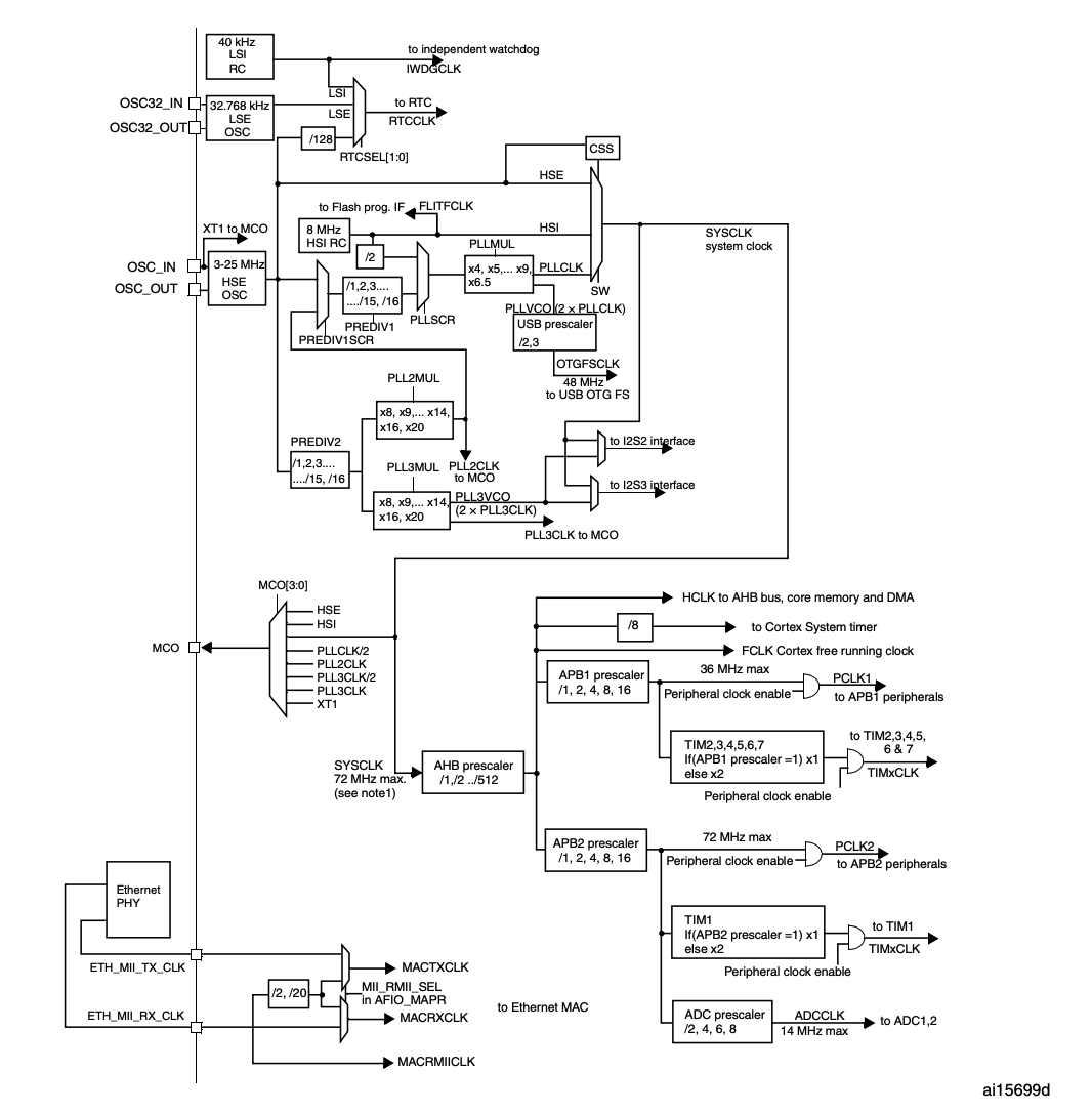
Looking at the diagram, we can split these sources into two categories:
- Speed: High-speed sources (for performance) and low-speed sources (for saving power).
- Origin: Internal sources (they already come in the chip) and external ones (you need to connect a quartz crystal).
Let’s get to know each one of them:
-
HSI(High Speed Internal): An 8 MHz internal oscillator. It is handy because it is already there, ready to use, but it is not the most accurate. -
HSE(High Speed External): The high-speed external oscillator (usually from 4 to 16 MHz). You connect a crystal on the outside, and it gives you a clock signal much more stable and accurate than theHSI. It is the recommended one for most serious applications. -
LSI(Low Speed Internal): A little 40 kHz internal “clock”. It uses little power and is meant to feed peripherals that don’t need speed, like the Watchdog (IWDG), which “watches” the system to check it hasn’t frozen. -
LSE(Low Speed External): Another low-speed clock, but this one is external and very accurate, at 32.768 kHz. It is the ideal choice for the Real-Time Clock (RTC), which needs to keep the time and date right, even while the rest of the chip is “sleeping”. -
PLL(Phase-Locked Loop): This guy is not an original source, but a multiplier. It takes the signal from theHSIor theHSEand multiplies it to generate a much higher frequency, reaching up to 72 MHz. It is the trick to make the STM32 run at full speed.
The Clock Path: From Start to End
The diagram we saw before shows the whole clock flow. Let’s follow the path:
-
Selecting the Main Clock (
SYSCLK): The high-speed sources (HSI,HSEand thePLL) arrive at a selector switch. Here, the system chooses which one will be theSYSCLK, the main clock that will feed almost everything in the chip. Most of the time, we configure it to use thePLLat 72 MHz. -
Distribution to the Buses: Once it is chosen, the
SYSCLKis distributed. It goes through frequency dividers (prescalers) to generate slower clocks for different parts of the chip:HCLK: It is the clock of theAHBbus, where the CPU, the memory and theDMAlive. Usually, it runs at the same speed as theSYSCLK(72 MHz).PCLK1: It is the clock of theAPB1bus, where the slower peripherals are (up to 36 MHz), likeI2C, theUSARTsandCAN.PCLK2: Clock of theAPB2bus, which feeds the faster peripherals (up to 72 MHz), likeGPIO,SPI1and theADC.
Special Clocks:
USB: The USB peripheral needs an exact 48 MHz clock. This signal comes straight from thePLL, going through a special divider.RTC: The real-time clock has its own selector switch, and it can use theLSE, theLSIor even theHSEdivided by 128.MCO(Microcontroller Clock Output): A real lifesaver for debugging! You can configure a pin (PA8) to “spit out” one of the internal clocks. That way, you can measure it with an oscilloscope and be sure everything is configured right.
Configuring Everything in Code (SystemInit)
All this configuration is done at the start of your code’s execution, inside a function called SystemInit. By default, STM32 projects already come with this function configured for the following scenario:
- Enable the
HSE(assuming an 8 MHz external crystal). - Configure the
PLLto multiply theHSEby 9 (8 MHz * 9 = 72 MHz). - Select the
PLLas theSYSCLKsource. - Configure the dividers of the
AHB,APB1andAPB2buses.
The final result is what we see in most projects:
| Clock Name | Default Speed |
|---|---|
SYSCLK (System Clock) |
72 MHz |
HCLK (AHB Bus Clock) |
72 MHz |
PCLK1 (APB1 Bus Clock) |
36 MHz |
PCLK2 (APB2 Bus Clock) |
72 MHz |
PLL Clock |
72 MHz |
And the most important thing of all: no peripheral works if its clock is not enabled! Whenever you are going to use a timer, a serial port or anything else, the first thing to do in code is to turn on its “clock”.
Comments
Comments are hosted by Disqus, which sets cookies and shares data with Disqus. Load comments? Read the privacy page for details.